
The Need
My 3D printer is not located in my home office, and I can’t always step away from meetings or other things that I’m doing to check on it. Now, I know what you’re thiniking. Why not just use Klipperoid on your phone? That does indeed work… but then I have to pickup my phone, unlock the screen… Yeah, I’m lazy. Previously, I had used a zigbee RGB lightbulb to indicate status with no real way to display progress. I could have adjusted the bulb brightness, but let’s face it, I can’t tell the difference between 54% and 55% brightness to know what number it’s trying to convey to me. What I wanted was something that I could quickly glance at and know the state of the printer. At first, I thought about using an addressable RGB light strip, but price, portability, and implementation quickly shot that down. After a bit of searching, I came across the ESP8266 devices. I love me some IoT, and Home Assistant with the ESPHome addon looked like a perfect match. It was also cheap to play with. For less than $20, I could build what I needed and if it didn’t work, I didn’t break the bank and would likely use the chips elsewhere.
Bill of Materials
To implement this project, we need to get a whopping two items:
ESP8266 NodeMCU v2 12F – $3.60 per piece (sold in bulk for $36/10)
MAX7219 LED Matrix Display – $11
If you want to save some money, and don’t mind waiting, you can get both items on AliExpress for quite a bit cheaper.
A Quick Note About NodeMCU Variations
I had purchased a couple other versions of the NodeMCU boards and found a couple things. First, there are a few variations of the boards that are available that use different UART chips. The version 3 boards make use of the CH340 chip which I have found (and others have reported) to be a bit flakey. The version 3 boards are also an odd size that will not mount to a breadboard without modification or jumper wires. This can make prototyping a bit complicated. They also swap out the two reserved pins for a 5v out and an additional ground. If you use USB to power the board, you can use the VIN and GND pins on the lower left for the same thing. There are also a couple variations of the v2 boards. The most common one uses the ESP-12E chip. I opted to go with the ESP-12F versions. The only difference between the two is the antenna design. Supposedly, the 12F antenna is better optimized. There is also a variation of the v2 board which swaps out the CP2102 for another SiLabs chip.
Wiring
We’ll make use of 5 of the pins on the board.
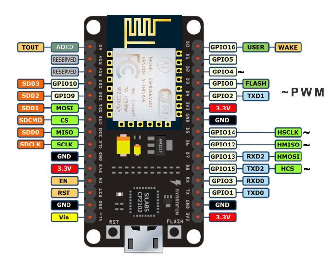
D0 (GPIO16)
D1 (GPIO5)
D2 (GPIO4)
3V3
GND
To connect the LED Matrix, I opted to use a 7 position dupont connector instead of seperate 3 and 2 position ones. The wires are connected as follows:
VCC → 3V3
GND → GND
DOUT → D1
CS → D2
CLK → D0
I also replaced the normal pins on the board with the 90 degree version like what came originally on the LED Matrix and rotated the pins on the LED matrix so that they faced along the board instead of away from it. I did this to minimize the extra space needed in the enclosure.
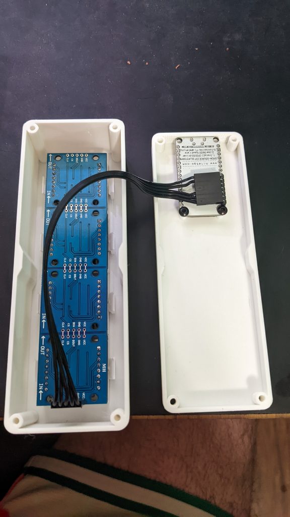
Enclosure
I found a simple enclosure on thingiverse made by knoopx. Since the enclosure was made for a v3, I did have to load it into tinkercad and modify the mount points for the nodeMCU. I also found that the tabs that hold the LED matrix in place were slightly loose for my display, but they held it ok, so I didn’t end up modifying that. I also added holes in the back cover to allow the screws to hold the cover together. All screws are standard M3. My modified version can be had on tinkercad. I printed the enclosure using a white PLA to allow the LEDs to shine through. I will likely play with some darker colors in the future as well.
Setting Up Home Assistant
The first thing we need to do is install ESPHome. If you already have ESPHome installed, skip ahead. To install, go to Settings → Add-ons → Add-on Store → ESPHome → Install. Once installed, you may need to restart your HAss instance.
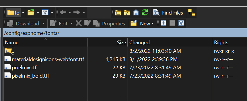
Next, we need to install two fonts. The first font is optimized for matrix displays with blocky characters. The second allows us to utilize the material design icons. To do so, download the two font files below
Material Design Icons
PixelMix
Once the fonts are downloaded, we need to upload them to Home Assistant. To do so, simply use WinSCP or another tool to copy the TTF files to /config/esphome/fonts.
Making Firmware
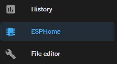
Now, from the left hand navigation menu, we can select ESPHome.
If you haven’t used ESPHome before, the first thing we’ll want to do is setup our Wi-Fi information. To do this, click on Secrets in the top right. Enter in your Wi-Fi information.
# Your Wi-Fi SSID and password
wifi_ssid: ""
wifi_password: ""
Save and close
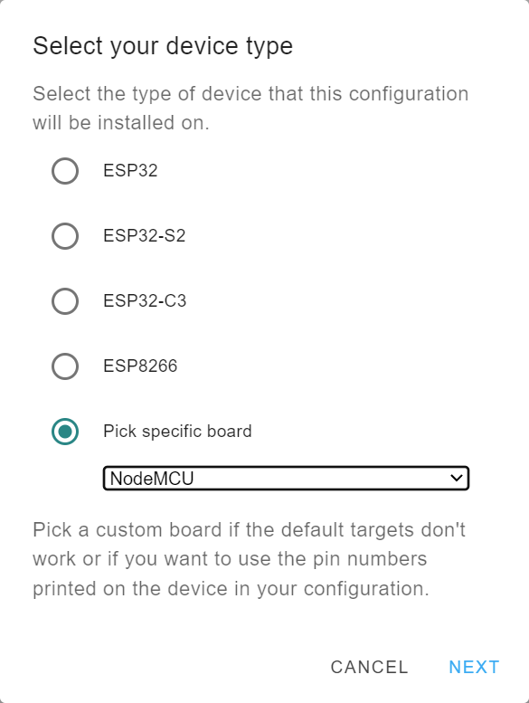
Next click on New Device in the lower right and then Continue. Give your device a name when prompted. Make note of the name as we’ll need to reference it for our automations later. Now we select the board type. We’ll select “Pick specific board” and then “NodeMCU” under ESP8266.
When prompted to install, click Skip.
Click on edit and you’ll be presented with the YAML for the firmware config. You can leave everything alone, and insert the following after captive_portal:
spi:
clk_pin: D0
mosi_pin: D1
display:
- platform: max7219digit
cs_pin: D2
num_chips: 4
intensity: 5
lambda: |-
if (id(office_ledmatrix).has_state()) {
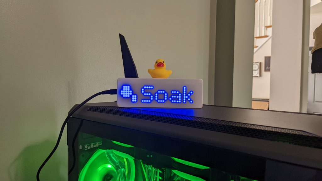
if (id(office_ledmatrix).state == "Soak") {
it.fill(COLOR_OFF);
it.print(0, 1, id(icon_font), "\U000F18B8");
it.print(9, 0, id(digit_font), "Soak");
}
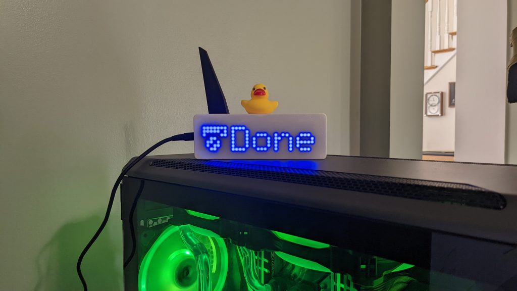
if (id(office_ledmatrix).state == "Done") {
it.fill(COLOR_OFF);
it.print(0, 1, id(icon_font), "\U000F042B");
it.print(9, 0, id(digit_font), "Done");
}
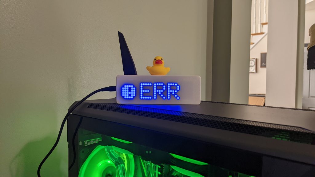
if (id(office_ledmatrix).state == "Error") {
it.fill(COLOR_OFF);
it.print(0, 1, id(icon_font), "\U000F0029");
it.print(9, 0, id(digit_font), "ERR");
}
if ((id(office_ledmatrix).state != "Soak") & (id(office_ledmatrix).state != "Done") & (id(office_ledmatrix).state != "Error"))
{
it.fill(COLOR_OFF);
it.print(0, 1, id(icon_font), "\U000F0E5B");
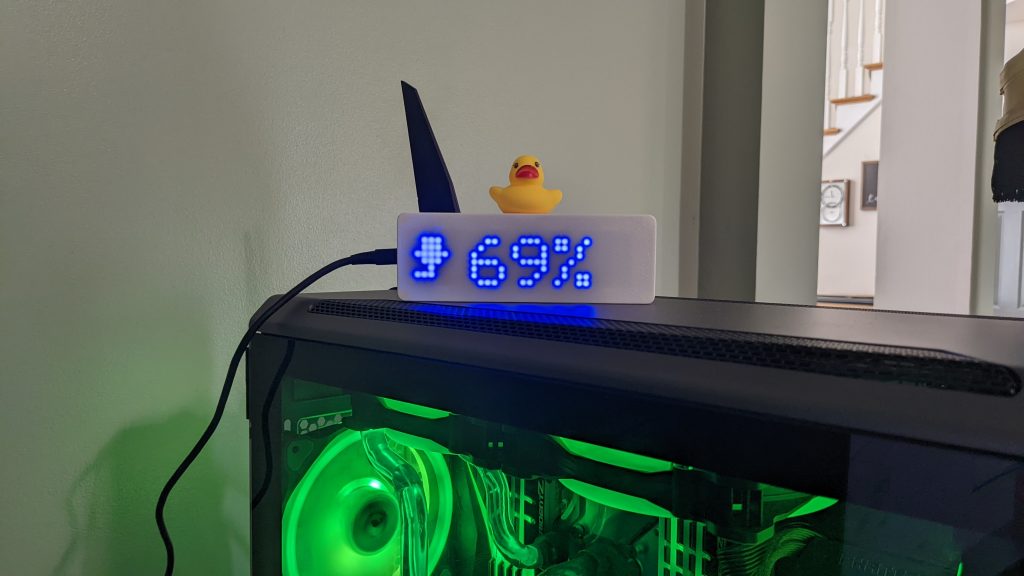
it.printf(9, 0, id(digit_font), "%s", id(office_ledmatrix).state.c_str());
}
if (id(office_ledmatrix).state == "") {
it.fill(COLOR_OFF);
it.turn_on_off(true);
}
} else {
it.fill(COLOR_OFF);
it.turn_on_off(true);
}
font:
- id: digit_font
file: "fonts/pixelmix.ttf"
glyphs: '"/@&?!%()+=,-_.:°0123456789ABCDEFGHIJKLMNOPQRSTUVWXYZ abcdefghijklmnopqrstuvwxyz'
size: 8
- id: icon_font
file: 'fonts/materialdesignicons-webfont.ttf'
glyphs: "\U000F0E5B\U000F18B8\U000F042B\U000F0029"
size: 8
text_sensor:
- platform: homeassistant
name: "office ledmatrix"
id: office_ledmatrix
entity_id: input_text.office_ledmatrixMake note of the encryption key. You’ll need that when adding the device later. There may be a few things you want to change in the above code.
font:
glyphs – If you want, you can completely omit this to include every available character. To keep the firmware binaries small, I’ve elected to select only the required glyphs that I’ll use for my display. For the material design icons, you can get a full list of all the glyphs and their IDs. To use them in strings, pre-pend them with \U000. Be sure that any strings that use them are enclosed with double quotes and not single quotes so that they aren’t interpreted as literals.
text_sensor:
name – Change this to whatever you want.
id – this can also be changed to whatever you like. It will need to comply with Home Assistants rules around device naming. If you change this, be sure to update lines 11, 12, 17, 22, 27, 31, & 33 above. Basically, do a find/replace.
entity_id – If you change the id, change this as well to be ‘input_text.<id>’
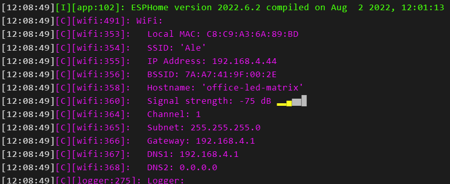
Once you’re happy with the YAML, click Save then Install. Next, select Manual, and Legacy format. Since we don’t have firmware on the board yet, we can’t flash it wirelessly. There is an option to use the ESPWeb interface to do so, but I had issues getting that method to work. I found that using the ESPHome flasher was the easiest way to do the initial flash. Plug your board into your computer and run the flasher with administrative privileges. Select your COM port and then the BIN file that was downloaded after ESPHome compiled it and click flash. Your board will be flashed and you should then see a log. The board will connect to your wifi and you’ll notice your IP Address right under the SSID.
The Helper and Device/Integration
Next we’ll setup the helper in Home Assistant.
In Home Assistant, go to Settings → Devices & Services → Helpers.
Click + Create Helper and select Text as the type.
For the name, enter in the id that you specified in the YAML. In my example, it was office_ledmatrix.
Click Create and you should see your new helper with an Entity ID of something like input_text.office_ledmatrix (the same entity_id as we specified in the YAML).
Next, return to the Integrations screen, and click + Integration. You’ll want to add an ESPHome integration. If your router/computer multicast DNS, you can use the hostname.local, otherwise, use the IP address of the device. After you click submit, you’ll need to enter the encryption key from the devices YAML that we generated earlier.
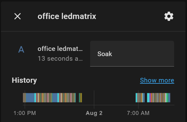
Now you should be all set. To test, we can go back to Helpers, select our helper, and click on the control icon.
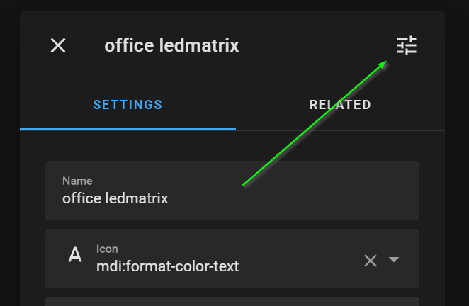
From here, we can manually set the value to test:
The Automations
Finally, we need to setup the Automations. The automations I’ve included below are what I setup in my HAss instance to interface with my printer which runs Klipper and fluidd. If you’re running a different firmware or are using octoprint, you may need to adjust the automations depending on which sensors are available. There are a total of 5 automations. You will likely need to update the device_id and entity_ids to match your setup.
alias: 3D Printer - Soaking
description: ''
trigger:
  - type: running
    platform: device
    device_id: 36c487f404c4b67400b5354516fe7363
    entity_id: binary_sensor.reprap_print_status
    domain: binary_sensor
condition: []
action:
  - service: input_text.set_value
    data:
      value: Soak
    target:
      entity_id: input_text.office_ledmatrix
mode: single
The Soaking automation is triggered when the Print Status starts running. When that triggers, the automation sets the value of our helper to ‘Soak’.
alias: 3D Printer - Printing
description: ''
trigger:
  - platform: state
    entity_id:
      - sensor.reprap_print_progress
condition:
  - condition: state
    entity_id: sensor.reprap_print_state
    state: printing
action:
  - service: input_text.set_value
    data:
      value: '{{ states(''sensor.reprap_print_progress'') }}%'
    target:
      entity_id: input_text.office_ledmatrix
mode: single
The Printing automation is triggered when the print progress is updated (each %) as long as the state is ‘printing’. Here, we set the value of the helper to the value of the print progress state and append a % sign to the end of it.
alias: 3D Printer - Print Complete
description: ''
trigger:
  - platform: state
    entity_id:
      - sensor.reprap_print_state
    to: complete
condition: []
action:
  - service: input_text.set_value
    data:
      value: Done
    target:
      entity_id: input_text.office_ledmatrix
mode: single
The Print Complete automation runs when the print state changes to ‘complete’. We set the value of the helper to ‘Done’.
alias: 3D Printer - Error
description: ''
trigger:
  - platform: state
    entity_id:
      - sensor.reprap_print_state
    to: error
condition: []
action:
  - service: input_text.set_value
    data:
      value: Error
    target:
      entity_id: input_text.office_ledmatrix
mode: single
In the rare event that we get an error, we set the helper to, well, ‘Error’.
alias: 3D Printer - Turn Off Office LED Matrix
description: ''
trigger:
  - platform: state
    entity_id:
      - sensor.reprap_print_state
    to: standby
    for:
      hours: 0
      minutes: 15
      seconds: 0
  - platform: state
    entity_id:
      - sensor.reprap_print_state
    for:
      hours: 0
      minutes: 15
      seconds: 0
    to: complete
condition: []
action:
  - service: input_text.set_value
    data:
      value: ''
    target:
      entity_id: input_text.office_ledmatrix
mode: single
Lastly, we check if the state of the printer has been either ‘standby’ or ‘complete’ for 15 minutes or more. If so, we blank out or erase the value of our helper. This tells our ESP to turn off the screen or power off all the LEDs.
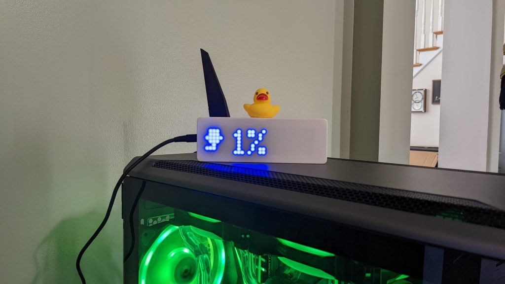
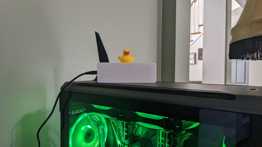
Conclusion
It’s a cheap little box that I can take anywhere in my house and just plug in to have a status display. I typically keep it in my office, but I’ve also taken it down to my woodshop while working to keep an eye on the printer from there. It took a bit to piece some of the bits of information I found together. I think I also went through 20 iterations of firmware to get the screen to a point that I was happy. Ultimately, I’ve been very happy with the little boards. I did originally purchase a different board that what I linked above, but blew two of them up due to a faulty/cheap USB cable. One word of advice, if you get one of those dinky little USB micro cables that comes with most rechargeable items… throw it away. Now that I’ve switched it over to a more robust cable, I’ve not had any issues. I plan on two more projects in the near future for this. First, I plan to get my kegerator integrated into HAss, and next, I might create a different display setup to allow for more information.


